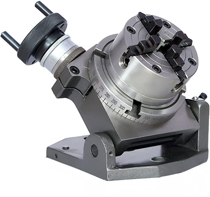

4 Brand New, High-Quality Pieces “Precision Tilting Rotary Table with 100 degrees of freedo.
This product has the ability to tilt between 0-90 degrees and can be locked in any position.
100 mm is the diameter of the table. The table is graduated in all directions. Worm Gear Ratio is -1:36, which means that one rotation of the handle will turn the table by a full ten degrees.
The kit includes an 80 mm 4 jaw Independent Chuck as well as fixing T nuts and bolts.
SHIPPING IS QUICK THROUGH A TRACKABLE AWB NO. TO THE UNITED STATES AND WORLDWIDE.
Description: This product has the ability to tilt between 0-90 degrees and can be locked in any position. 100 mm is the diameter of the table. The table is graduated in all directions. Worm Gear Ratio is -1:36, which means that one rotation of the handle will turn the table by a full ten degrees. 2-5/8 inches at the center of the vertical position “(approximately 66 mm), excluding the Chuck assembly. The hand wheel is graduated in 10-minute increments and has the option of being reset to zero. It is possible to mount it in both horizontal and vertical positions.
This is something that I find myself changing my rating of as more and more I use it. As a result of being forced to disassemble the table, I discovered that some aspects of the design were terrible, others were downright incorrect, and a few areas could have used a little more attention to detail. After arriving in my possession, it could have benefited from better packaging and could have used some reworking and finishing touches. It should be noted that this item is small, but this is specifically stated in the size descriptions. The product would have received at least 4 out of 5 stars if it had been packaged more securely and did not suffer from the flaws I’ve listed below.
Design Issues – There are several design issues to consider.
One roller bearing is used to support the rotary plate at the far end of the spindle shaft, and that roller bearing is a single-row roller bearing. Because when the worm gear is disengaged and you spin the worm gear free hand, there are noticeable dents around the race that the balls hit and click through, it appears as though the bearing was hammered in or that the races are extremely soft in construction. When pulling the rotary plate in tight enough against the housing to allow the rotary plate shoulder to act as a face bearing while not pulling it in too hard that the rotary plate becomes stuck, extreme caution must be exercised. Once I had been using this for a while and had begun to experience a random onset of extremely strange harmonic vibrations, I noticed that the rotary plate had the ability to bend upward and away from the housing. Because the rotary plate is supposed to function as its own bearing while sliding on the housing, it must be set precisely, which was not the case when it was shipped from the factory. Because the plate preload setting/locking feature is a simple coarse threaded flat head hex screw that pulls the spindle shaft through the end bearing and snugs the rotary plate against the housing, it is extremely fiddly to set and can easily go from loose and sloppy to over tightened and nearly seized up. Using only a coarse thread to set up a rotary table, and relying on a single ball bearing at the far end of a shaft and the rotary plate sliding on the housing, is probably the worst method of setting up a table.
The rotation lock is in an inconvenient location, with insufficient contact area to prevent damage to the main rotary plate. The locking screw is secured to a small portion of the main rotary plate that is recessed into the housing by the housing’s retaining screw. The center of the screw is just a hair above the bottom edge of the recessed shoulder when it is in the center of the screw. It worked fine at first, but after a few times of tightening the locking screw down, I noticed that it had become spongy and that it would not stop turning even when I lifted the rotary plate off the housing. It turned out that the locking screw had actually broken off portions of the cast iron recess shoulder, and that the screw was simply threading in under the plate when I took it apart. This was revealed to me when I noticed the rotary plate lifting and vibrating while machining, and I investigated further. In addition, the lock thread passes through the thinnest part of the housing to secure the lock. I received mine with the threads broken out of the box, and the top section of the threads cracked off. This was a simple problem to resolve. I simply repositioned the threads in a more substantial area. The issue of there not being enough engagement surface on the rotary plate presented a more difficult problem to solve. I machined a pocket into the rotary plate shoulder and created a matching brass locking tab that the locking screw pushes against and, as a result, pushes into the shoulder of the rotary plate. This prevents the screw from chipping away at the clamp edge, and it also prevents the rotary plate from lifting up while being held fixed. This could have been easily avoided if the rotary plate shoulder had been longer, allowing the locking screw to fully engage with the cylindrical surface on which it was mounted.
Inconsistencies between the graduations on the crank handle and the graduations on the rotary table are evident. The numbers 1, 2, 3, 4, and 5 are marked on the crank, with 30 minute marks between each whole number and then 5 minute minor marks for the remainder of the way. A complete rotation of the crank handle, on the other hand, rotates the table by 10 degrees. For example, rotating from 1 to 2 would be a 1 degree change by marking, but it would be a 2 degree change on a rotary table because of the way the table is set up. This means that the crank handle ratio is actually twice as large as the markings suggest. You must rotate from 2 degrees to 2 degrees 30 minutes, or half of a full degree marking, if you want to move one full degree, for example. Then there are the minor marks, which are actually 10 minutes of rotation time. This isn’t a deal breaker, but it’s something to be aware of before proceeding. In the event that someone simply picked up the table and started using it, they could be expected to rotate twice as far as is necessary based on the crank marks. You simply need to stamp over the existing numbers and change them to be 1 through 10 instead of 1 through 5. This will fix the problem. Without going into too much detail, I’m not sure how something like this came to be, other than out of sheer laziness.
Problems with paying attention to the details .
As a result of the packaging failing during shipping, and the 4-jaw chuck not being attached, it appears to have slammed around inside the box, bending the rotation locking screw and causing some dings to appear on the surface of the box. All of the Styrofoam packing material inside was completely destroyed. The bottom surface of the 4-jaw suffered a few dings as a result of the bouncing, but nothing appears to be seriously wrong with it. Aside from that, everything appeared to be nicely finished in terms of appearance when it was first pulled from the box.
The tightening screws on the jaws and the jaws on the 4-jaw are the two areas that require attention. It’s either that the screws are colliding with each other at full close or that the jaws are getting hung up on the edges of the guide rails, or it’s a combination of the two depending on which jaw is being adjusted. In order to correct this, the screw ends must have a radius on the nose of the screws, and the guide rails must be deburred and adjusted to eliminate any high spots.
The jaw tips on two of the jaws are not machined evenly. The tips do not align with the rest of the design in the center. During the manufacturing process, an excessive amount of material was removed from one of the angled sides. Due to the fact that it’s an independent 4-jaw chuck, it’s not a big deal, but it would have been nice to have them squared up from the beginning. It should be a simple matter to rectify the situation.
Expect to use the small tilt lock lever for nothing more serious than adjusting the initial plate angle, if at all. In order to get the hex to pull in tightly enough to prevent the whole thing from kicking over when you start to engage the cutting tool, you’ll need to use a 16mm wrench. When it comes to the slot where the locking hex is located, the wrinkle paint is also quite thick, so expect to see it crack and then scrape it away to create the best locking surface possible.
When it was delivered, the rotary handle backlash had not been properly adjusted. Fortunately, it’s fairly simple to tighten down, and you can reduce the backlash from 3-5 degrees to just under a degree in a single pass. Despite the fact that there are only a few sharp edges on the hobbed flutes, the worm and worm gear appear to be well machined. The worm is made of steel, and the worm wheel is made of brass, resulting in a self-lubricating system that works well.