
The best values in the class are now even easier to use. With less than 30 minutes of work out of the box, this is ready to go. For anyone who wants to learn a new skill, work on an art project, make a DIY gift, or start their own small business.
Grbl v1.1 is still the base for the PROVer, but it now has more powerful but quiet Toshiba TB6S109 drivers with more life and performance. It also has more Optocouplers to protect your mainboard from hard stops without risking damage and eliminate signal noise for more consistent projects and longer life.
You can make more with the all-aluminum body, which is more stable and allows you to mill a wider range of materials. You can also make cleaning up even easier with acrylic safety baffles that help contain dust and keep people safe.
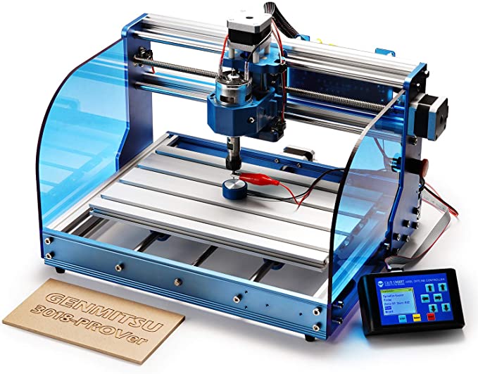
It’s easy to take control of your 3018-PROVer Desktop CNC machine with the controls right in front of you. The 1.8″ display will show you the readouts clearly and let you control your mill without a computer. If a project gets out of hand, the PROVer has an emergency stop control that is very visible and easy to reach. This control can shut down your machine right away.
CAD/CAM software is used to design and then convert your ideas into instructions (GCode) that the router can read and follow so that it can make the things you want (common options are Carveco, Fusion360 and Easel). You can check out the SainSmart Resource Center (see the User Guide) if you get stuck, or you can contact us with any questions that come up.
Overvie.
The Genmitsu 3018-PR.
If you want a better version of a product that already had good design and safety, you can get Ver. The new version also has better parts, like better mainboards and pre-assembly. It’s great for beginners, hobbyists, and small business owners who want to learn how to use a CNC machine.
SPECIFICATIO.
This is the area that can be used for engraving: 260 x 155 x 35mm (10.2/6.1/6.1).
The frame is 400 x 330 x 240mm (15.7 x 13.0 x 9.4″).
The frame is made of aluminum.
The Z-Axis Componen. It’s made out of ABS.
The spindle has a 775 motor that runs at 12V to 24V and has a speed of 10000 RPM.
When the power is turned on, it has a rating of 60W. When it’s turned on all the way, it ha.
Motor: 1.3 A, 12V, 0.25 Nm torque, stepper motor (2.2 in-lb.
These are the types of drill bits: Tip 0.01mm, 20°, Diameter 3.1775mm.
It works with Windows XP, Windows 7 32/64-bits, Windows 8, Windows 10, Linux, MAC OS, and more.
For example, this is the software that lets you run Grbl (Candle.
24V/5A, with CE, FCC, and PSE certifications, is the power source.
Hobbyists, Crafters, Woodworkers, Industrial Designers, Educators, Engineers, Jewelers, and more will love this tool.
WHAT’S IN IT.
It has 1 x Genmitsu 3018-PROVer CNC Router (Some parts need to be assembled.
1 x Offline Control Uni.
Box of tools (includes emergency stop button, Z probe, etc.
1 x Screw and Nut Bo.
4 x CNC Clamps are here.
These 10 bits have a 1/8″ shank and have cutting edges that are 0.02mm wide by 20 degrees.
Date: January 18, 2020. Review and corrections to SainSmart 3018-PROver will be done.
The materials are good: thick aluminum, good-quality electronic and mechanical parts, and good-quality screws and bolts. The 3018-PROver isn’t nearly as “assembled” as the data shows. It’s up to you to download the assembly video or the manual and see for yourself how long it takes to put together. There are a few hours of work and you’ll need to look at the online manual, the video, and this errata while you do it. The three major subsystems have been put together mechanically, but the electrical components, wiring, and a lot of small parts haven’t been put in place. Two major subsystems need to be bolted together. There are a lot of things you have to think about, so if you’re easily frustrated, don’t work on this one.
People who want to use PROver have to use open source software, but it also has its own motion controller software: GRBL 1.1. Do not need to connect your computer when the router is cutting. The Open Source CAD software doesn’t come with the machine. Most people will use this software to make things.
There is also a “3018 Pro MX3” version that costs $175, has a different main controller board and a different hand controller, and needs a Windows computer to run Mach 3 while the router is cutting. This version also needs the Mach 3 software. The 3018 PROver is a better choice for most people, because it doesn’t have to pay for and deal with all of this extra money and work. Mach 3 isn’t the CAD software. It’s for controlling how things move. Find that, too.
3018-PROver has an Arduino controller in it, which is why it can do things. The main controller runs the GRBL 1.1 software that was made for Arduino. It comes with its own hand controller, which you can use to move the machine. If you have a hand controller for another model, like one for the MX3 version, it is not going to work with this one.
As far as I can tell, the source code for GPL-licensed software in this unit is not on the SainSmart web site. It looks like SainSmart needs to learn how to comply with the licenses to the GPL binary software they distribute, and to directly distribute the source code on their own site. I don’t know what’s different from the source code for GRBL 1.1, but I think there might be some for the hand controller.
After using this machine, it will be covered in chips, and it will need to be cleaned up. This includes wiping down the T-slots with some kind of wipe. To make a chip vacuum for mine, I will have to make one myself. There isn’t anything like that to buy.
To find the video on how to put together the Sainsmart Genmitsu CNC Router 3018-PROVer Build, look for it on YouTube. Wiki pages for the device can be found at wiki.sainsmart.com, which is a few hits down from the top of the search on Google. It’s also on the wiki. The index is based on SKU numbers, so you can find this there as well. There are videos on YouTube that show how to put together other models. You might find them useful.
Most of the tools needed for assembly are already there. If you want to get rid of the shipping locks, you’ll need to cut off two wire ties. You’ll also need to get some light oil to lubricate the lead screws, as well as some electrical tape to wrap moving wires together.
Download the manual and put it on a big screen to see it bette. Because that’s the only way you’ll be able to see the photos well enough to put the unit together. There is a printed manual that comes with the device. The photos are small and low-resolution, so it’s hard to figure out what you should be doing from them.
Here are the mistakes I made while I was building.
If you don’t have one, you’ll need to bring one with you.
Step 2: You are told to put 6 wire holders on, but the picture only shows two of them. The video is also useless. The second two go on the other side, just like the first two. Outside of the frame, they go next to each other. They’re next to the stepper motor, which is on the other side of the frame.
When you’re done with Step 3, the metal piece has four wire holders on each side. The pictures don’t show this as well as they should.
Steps 5 and 6: The long end of the distance tool is held against the back of the frame, inside the channel, for both of these steps. The last slider nut should be against the end of the distance tool. This is how it should look. For some reason, everything lines up and the 12 bolts go in a lot easier than I thought.
On the slide nut, a square goes out.
The last step is to peel off the protective film from both sides of the acrylic sheets. When you do that, they become clear and blue. The sheet should be held so that it fits the shape of the leg of the Y-Z set up. That is the correct way to stand. When you put the bolts through from the outside, turn the slide nuts on the other side by hand, only one turn. In this step, place the slide nuts horizontally, then push the acrylic sheet down so that the slide nuts fit into the groove. To turn the bolts, turn the slide nuts.
Step 10: There’s a mistake on this page. When they say Y+ and Y-connecting wires, they mean X. They are correct. The VER numbers are correct, but the word “Y” should be “X..
They connect to two beams, each of which has four channels. Behind the main controller, run the wire for the X-limit switch. It should loop around and come out in front, where there is a USB port on one side. The cover strip goes over the wire that goes through the top channel of the bottom beam.
Depending on where the limit switches are, you may need to remove some wire holders in order to make room for the plugs. After you’re done, put the wire holders back where you found them.
Step 13: There are two different plugs on each end of the wires from the stepper motor.
There is a black nut on the barrel of the emergency stop button that is called “black cover. It and the square lock washer should be taken out. Make sure the switch is in the plate, and then put the lock washer on it from the back. Make sure the pointy corners are facing the metal.
This button is different: You push it to stop, then twist it to let go.
Step 16: That’s it. There’s a lot of space here. You should put all of the Z wires through a piece of nylon braided web to keep them from getting snagged by other things. But the piece I was given, even though it can be expanded a little, isn’t big enough to do this. I used electrical tape to wrap the wires around each other and keep them safe.
Operatio.
It’s a good idea to play with the router manually before you connect it to your computer. This doesn’t make sense, though. There were files on the SD card that would run into hard limits if the router was set to start at home. This meant that the limit switches would be tripped. Before you start, you’ll need to move X, Y, and Z close to the center of their work.
The limit switches are hard to understand. A limit will come up at some point. If you can’t get past it, run the reset function. Keep moving until it stops again. When the limit switch is set, it will stop the system again. It’s better to run the reset function again than not run it at al. Then you can move the axis as you want. As I write this, I don’t know if this will be any easier if I set things up.